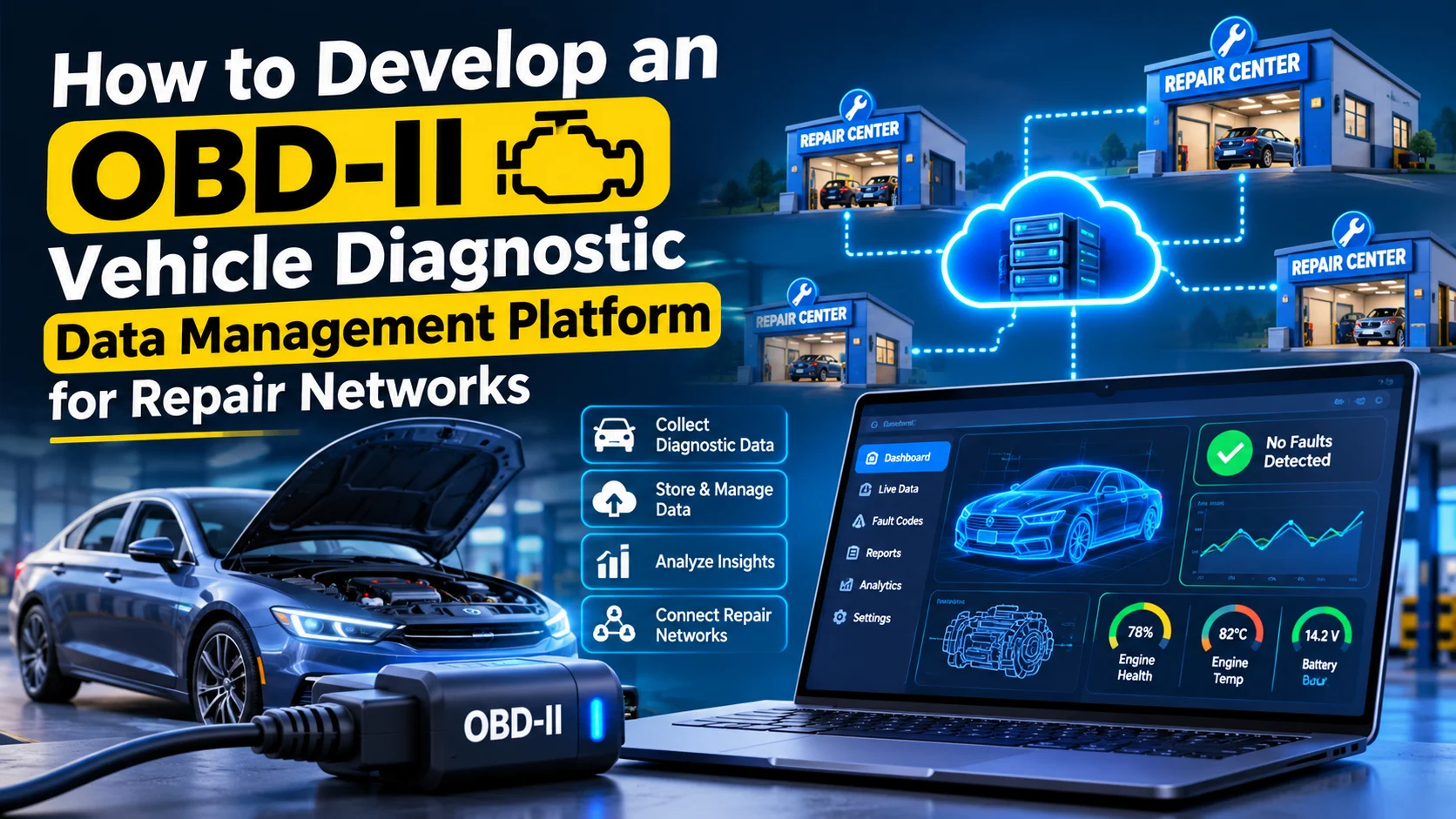
Modern automotive repair networks handle vehicles with increasingly complex electronic systems. Identifying faults, understanding diagnostic trouble codes, reviewing sensor readings, and maintaining accurate repair records require reliable diagnostic information.
OBD-II (On-Board Diagnostics II) provides standardized access to vehicle diagnostic information through a diagnostic connector. However, repair networks often use different diagnostic devices, workshop systems, and data formats. Managing this information across multiple repair centers can become difficult without a centralized platform.
An OBD-II vehicle diagnostic data management platform helps repair networks collect, process, store, and analyze vehicle diagnostic data from connected vehicles and diagnostic devices. It allows technicians to review fault codes, monitor sensor readings, maintain diagnostic histories, and connect diagnostic findings with repair orders.
In this guide, we explain how to develop an OBD-II vehicle diagnostic data management platform for repair networks, including its core features, architecture, database design, technology stack, integrations, security requirements, and development considerations.
1. What Is an OBD-II Vehicle Diagnostic Data Management Platform?
An OBD-II diagnostic data management platform is a software solution that collects and organizes diagnostic information retrieved from a vehicle’s onboard computer through compatible diagnostic interfaces.
The platform can receive information from OBD-II scanners, Bluetooth or Wi-Fi diagnostic adapters, workshop diagnostic equipment, and supported telematics devices.
Common diagnostic information includes:
- Diagnostic Trouble Codes (DTCs)
- Engine parameters and sensor readings
- Vehicle speed and engine RPM
- Engine coolant temperature
- Fuel system information
- Freeze-frame diagnostic data
- Readiness monitor status
- Vehicle identification information, where supported
- Diagnostic timestamps and scan history
The platform centralizes this information so technicians and repair managers can access vehicle diagnostic records across multiple workshops.
It is important to distinguish OBD-II diagnostic data from complete vehicle diagnostics. OBD-II provides standardized access to certain emissions-related and powertrain information, while manufacturer-specific systems may be required for additional modules and functions.
2. Identify Business Requirements for Repair Networks
Before development, understand how diagnostic data moves through the repair network.
Different repair businesses may have different operational requirements.
| Target Business | Main Requirements |
|---|---|
| Multi-location repair networks | Centralized diagnostic records across workshops |
| Independent garages | Fault code scanning and diagnostic history |
| Automotive service chains | Technician and workshop performance monitoring |
| Fleet maintenance companies | Vehicle health monitoring and maintenance records |
| Automotive diagnostic centers | Scan reports and fault analysis |
| Dealership service departments | Diagnostic integration with service workflows |
The platform should support multiple repair locations, technician accounts, vehicle records, and diagnostic devices.
For example, when a vehicle visits one branch, its previous diagnostic reports should be accessible to authorized technicians at another branch.
3. Essential Features of the Platform
A successful platform needs reliable data collection, diagnostic processing, workshop management, and centralized reporting.
A. Vehicle Registration and Identification
Build a centralized vehicle management module to maintain vehicle information.
Important fields include:
- Vehicle make and model
- Manufacturing year
- Registration number
- VIN or chassis number
- Engine type
- Fuel type
- Transmission type
- Odometer reading
- Customer or fleet ownership details
Where supported, the platform can retrieve vehicle information from compatible diagnostic devices.
VIN decoding services can also help populate vehicle specifications, but the application should validate retrieved information before saving it.
B. OBD-II Device Integration
Device integration is one of the most important parts of the platform.
The application should communicate with compatible diagnostic adapters and scanners to retrieve vehicle information.
Common connection methods include:
- Bluetooth Classic
- Bluetooth Low Energy (BLE)
- Wi-Fi
- USB
- Diagnostic equipment APIs
- Telematics gateway integrations
An OBD-II adapter typically communicates with the vehicle through standardized protocols such as:
- ISO 9141-2
- ISO 14230-4 (KWP2000)
- ISO 15765-4 (CAN)
- SAE J1850 PWM
- SAE J1850 VPW
The platform should identify supported protocols and handle differences between diagnostic devices.
Not every adapter supports every protocol or diagnostic function, so compatibility testing is essential.
C. Diagnostic Trouble Code Management
Diagnostic Trouble Codes help technicians identify detected vehicle system faults.
The application should provide a centralized DTC management module.
Important capabilities include:
- Reading stored trouble codes
- Reading pending trouble codes
- Reading permanent trouble codes where supported
- Displaying code descriptions
- Categorizing faults by vehicle system
- Recording diagnostic timestamps
- Tracking previously reported codes
- Comparing codes across multiple inspections
For example, a technician may retrieve a code related to an engine misfire and review its description, associated sensor information, and previous occurrences.
The application should avoid treating a trouble code as a definitive diagnosis. A DTC indicates a detected condition and usually requires further inspection and testing.
D. Real-Time Sensor Data Monitoring
Develop a dashboard that displays supported live vehicle parameters.
Common parameters include:
| Parameter | Purpose |
|---|---|
| Engine RPM | Monitors engine speed |
| Vehicle Speed | Displays vehicle speed |
| Coolant Temperature | Tracks engine temperature |
| Throttle Position | Shows throttle opening |
| Intake Air Temperature | Monitors incoming air temperature |
| Fuel System Status | Displays supported fuel system information |
| Mass Air Flow | Shows measured air intake |
| Oxygen Sensor Data | Supports emissions-related diagnosis |
The system should display available parameters in numerical, graphical, or tabular formats.
Live data should include timestamps, units, and source information to avoid confusion when technicians compare diagnostic sessions.
E. Freeze-Frame Data Management
Freeze-frame data captures selected operating conditions when certain diagnostic faults are detected.
The platform should store available freeze-frame information alongside the related trouble code.
Useful fields include:
- Engine RPM
- Vehicle speed
- Coolant temperature
- Engine load
- Fuel system status
- Diagnostic trouble code
- Capture timestamp, where available
Technicians can use this information to understand the conditions under which a fault was detected.
F. Diagnostic Scan History
Maintain a complete history of diagnostic sessions for each vehicle.
A diagnostic session should include:
- Vehicle identification
- Repair center
- Technician
- Diagnostic device
- Scan date and time
- Retrieved trouble codes
- Sensor readings
- Freeze-frame information
- Inspection notes
- Diagnostic report
This allows technicians to compare current and previous scans and understand whether a fault is new, recurring, or no longer detected.
G. Diagnostic Report Generation
The platform should generate professional diagnostic reports in PDF format.
Reports can contain:
- Vehicle details
- Customer information
- Diagnostic session details
- Detected trouble codes
- Code descriptions
- Available live data summaries
- Freeze-frame information
- Technician observations
- Recommended inspection steps
- Report generation date
Reports should distinguish between automatically retrieved diagnostic information and technician-entered conclusions.
H. Technician and Workshop Management
A repair network needs centralized technician and branch management.
Useful features include:
- Workshop registration
- Technician profiles
- Role-based access
- Diagnostic session assignment
- Branch-level vehicle records
- Technician activity history
- Workload monitoring
- Diagnostic report approvals
Network administrators should be able to monitor diagnostic activities across multiple repair locations.
I. Diagnostic Alerts and Notifications
The platform can send notifications when important diagnostic events occur.
Examples include:
- New diagnostic session completed
- Critical fault code detected
- Repeated fault identified
- Diagnostic report submitted
- Vehicle requires further inspection
- Assigned technician completes diagnosis
- Device connection or data synchronization failure
Alerts should be configurable to avoid unnecessary notifications.
4. Build the Main Platform Modules
A modular architecture makes it easier to maintain and expand the platform.
| Module | Main Responsibilities |
|---|---|
| Vehicle Management | Vehicle profiles and identification |
| OBD-II Device Management | Device registration and compatibility |
| Data Collection Engine | Collect diagnostic information |
| Protocol Processing | Parse and normalize diagnostic responses |
| DTC Management | Store and organize trouble codes |
| Live Data Monitoring | Display supported sensor readings |
| Scan History | Maintain diagnostic sessions |
| Report Management | Generate and store reports |
| Workshop Management | Branch and technician administration |
| Analytics Dashboard | Network-wide diagnostic insights |
| Notification Service | Alerts and workflow updates |
Each module should have clear responsibilities and communicate through well-defined APIs.
5. Understand the OBD-II Data Collection Process
The platform must convert raw diagnostic responses into structured information that technicians can understand.
A typical diagnostic collection process works as follows:
- The technician connects a compatible OBD-II adapter to the vehicle.
- The mobile application or diagnostic device establishes a connection.
- The system identifies the communication protocol.
- The application sends supported diagnostic requests.
- The vehicle’s electronic control unit responds.
- The adapter forwards the responses to the application.
- The data processing engine interprets the responses.
- The platform converts raw values into readable diagnostic information.
- The application stores the diagnostic session.
- The technician reviews the results and generates a report.
For example, an OBD-II service request can retrieve supported parameter identifiers (PIDs). The platform then interprets the returned hexadecimal values according to the relevant standards.
A simplified example is:
Vehicle
   |
   v
OBD-II Diagnostic Connector
   |
   v
Bluetooth / Wi-Fi Adapter
   |
   v
Mobile Application
   |
   v
Diagnostic Data Parser
   |
   v
Backend API
   |
   v
Diagnostic Database
   |
   v
Technician Dashboard
The application should handle unsupported PIDs, incomplete responses, communication timeouts, and adapter disconnections.
6. Recommended Technology Stack
The technology stack should support mobile device communication, high-volume diagnostic records, and centralized workshop management.
| Component | Recommended Technologies |
|---|---|
| Mobile Application | Flutter or React Native |
| Web Dashboard | React.js or Next.js |
| Backend | Node.js with NestJS, Django, or Laravel |
| Database | PostgreSQL |
| Time-Series Storage | TimescaleDB or a suitable time-series database |
| Cache | Redis |
| Device Communication | Bluetooth, BLE, Wi-Fi, USB SDKs |
| Data Processing | Python or Node.js |
| Cloud Storage | AWS S3 or Google Cloud Storage |
| Notifications | Firebase Cloud Messaging |
| Hosting | AWS, Google Cloud, or Azure |
| API Communication | REST APIs and WebSockets |
Flutter is suitable when a single mobile codebase is needed for Android and iOS. However, some diagnostic adapters require platform-specific Bluetooth or USB integrations.
For large diagnostic datasets, a time-series database can help manage frequently collected sensor readings.
7. Design the System Architecture
A scalable platform should separate device communication, diagnostic processing, data storage, and workshop management.
       OBD-II Diagnostic Devices
                  |
                  v
        Mobile Diagnostic App
                  |
                  v
          Device Communication
                  |
                  v
         Diagnostic Data Engine
                  |
          -------------------
          |        |        |
          v        v        v
        DTC      PID      Freeze-Frame
      Processor Parser     Processor
          |        |        |
          -------------------
                  |
                  v
              Backend API
                  |
       -------------------------
       |           |           |
       v           v           v
    Vehicle    Workshop    Diagnostic
   Management  Management   Management
       |           |           |
       -------------------------
                  |
                  v
            Data Storage
                  |
       -------------------------
       |           |           |
       v           v           v
   PostgreSQL  Time-Series  Cloud Storage
                Database
                  |
                  v
        Centralized Network Dashboard
The architecture should allow multiple repair centers to submit diagnostic data securely without accessing each other’s unauthorized records.
For larger deployments, diagnostic processing and report generation can run as independent services.
8. Plan the Database Structure
The database should maintain relationships between vehicles, diagnostic devices, repair centers, technicians, and diagnostic sessions.
Recommended tables include:
| Table | Important Fields |
|---|---|
| organizations | id, name, status |
| repair_centers | id, organization_id, name, location |
| users | id, organization_id, name, role |
| technicians | id, user_id, repair_center_id |
| vehicles | id, VIN, registration_number, make, model |
| customers | id, name, email, phone |
| diagnostic_devices | id, device_name, connection_type, supported_protocols |
| vehicle_device_sessions | id, vehicle_id, device_id, connected_at |
| diagnostic_sessions | id, vehicle_id, repair_center_id, technician_id, scan_time |
| diagnostic_trouble_codes | id, session_id, code, status, description |
| diagnostic_pids | id, session_id, pid, value, unit, timestamp |
| freeze_frame_records | id, session_id, trouble_code, data |
| diagnostic_reports | id, session_id, report_url, created_at |
| technician_notes | id, session_id, technician_id, notes |
| audit_logs | id, user_id, action, timestamp |
For high-frequency sensor readings, consider storing the data in a time-series database rather than placing every reading in the main relational database.
Use indexes on VIN, registration number, diagnostic session ID, trouble code, and repair center ID.
9. Develop the Diagnostic Data Processing Engine
The diagnostic processing engine is the core technical component of the platform.
It should handle several responsibilities.
Protocol Detection and Communication
Identify the supported communication protocol and configure the adapter accordingly.
The system should handle:
- Connection initialization
- Adapter identification
- Protocol selection
- Diagnostic request transmission
- Response collection
- Timeout management
- Connection recovery
PID Parsing
Parameter IDs represent standardized diagnostic values.
The processing engine should:
- Identify the requested PID.
- Read the response bytes.
- Apply the correct conversion formula.
- Convert the result into a readable value.
- Attach the appropriate unit.
- Store the result with its timestamp.
For example, a supported engine RPM response uses the formula:
[
RPM = \frac{256A+B}{4}
]
Here, A and B represent the relevant response bytes.
The application should implement conversion rules according to the applicable OBD-II specifications instead of relying on assumptions about raw response formats.
DTC Decoding
The system should decode diagnostic trouble codes into standardized categories and descriptions.
Common categories include:
- P: Powertrain
- B: Body
- C: Chassis
- U: Network and communication
Standardized OBD-II access does not guarantee that every body, chassis, or network code is available through every vehicle or adapter. Manufacturer-specific diagnostic access may be needed.
Data Normalization
Different devices may return diagnostic information in different formats.
The platform should convert incoming data into a consistent internal structure containing:
- Vehicle ID
- Diagnostic session ID
- Parameter identifier
- Normalized value
- Unit
- Timestamp
- Device information
- Data source
This makes it easier to compare diagnostic records across repair centers.
10. Add Advanced Features
After implementing the core diagnostic platform, additional capabilities can improve its value.
A. AI-Assisted Fault Analysis
Machine learning can analyze historical diagnostic codes, sensor readings, vehicle details, and technician notes to identify patterns.
Possible capabilities include:
- Grouping recurring fault patterns
- Highlighting unusual sensor readings
- Suggesting relevant inspection areas
- Identifying frequently repeated repair issues
- Supporting diagnostic report summaries
AI-generated suggestions should be treated as assistance, not confirmed mechanical diagnoses.
B. Predictive Maintenance Insights
The platform can analyze historical diagnostic information to identify potential maintenance concerns.
For example, repeated fault patterns or abnormal readings may indicate that a vehicle requires further inspection.
Predictive insights should be based on validated data and appropriate vehicle-specific models.
C. Cross-Workshop Diagnostic History
Allow authorized technicians to view diagnostic records from other branches.
This is useful when customers visit different locations within the same repair network.
D. Fleet-Level Vehicle Health Dashboard
Fleet managers can monitor diagnostic activity across multiple vehicles.
The dashboard can show:
- Vehicles with active fault records
- Frequently reported diagnostic codes
- Vehicles requiring inspection
- Diagnostic history by vehicle
- Workshop-level performance
E. Remote Diagnostic Data Collection
For supported telematics devices, diagnostic information can be transmitted to the backend without requiring a technician to initiate every scan.
This feature requires compatible hardware, vehicle support, appropriate connectivity, and customer authorization.
11. Integrate Third-Party Systems
The platform becomes more useful when diagnostic information is connected with existing repair and business systems.
| Integration | Purpose |
|---|---|
| Dealer Management System | Synchronize vehicle and service records |
| Workshop Management Software | Connect diagnostics with repair orders |
| CRM Software | Retrieve customer and vehicle information |
| Fleet Management Systems | Access fleet vehicle records |
| VIN Decoding APIs | Retrieve supported vehicle specifications |
| Diagnostic Hardware SDKs | Communicate with compatible devices |
| Cloud Storage APIs | Store diagnostic reports |
| Notification Services | Send alerts and updates |
| Analytics Platforms | Analyze network-wide diagnostic performance |
Use secure APIs and webhooks where supported. Maintain integration logs to identify failed synchronization attempts.
12. Implement Security and Data Protection
Diagnostic data and customer vehicle information must be protected across all repair locations.
Important security measures include:
- Secure user authentication.
- Role-based access control.
- Organization and branch-level data isolation.
- Encrypted API communication.
- Secure Bluetooth and Wi-Fi pairing practices.
- Protected diagnostic report storage.
- Audit logs for data access and changes.
- Regular database backups.
- Secure device registration and revocation.
- Defined data retention policies.
The platform should also require appropriate authorization before collecting vehicle information or enabling remote diagnostic functions.
13. Test the Platform Before Launch
Testing should cover both software functionality and real-world hardware compatibility.
| Testing Type | What to Validate |
|---|---|
| Device Compatibility | Supported OBD-II adapters and scanners |
| Protocol Testing | Supported communication protocols |
| Functional Testing | DTC reading, PID parsing, and reports |
| Data Accuracy Testing | Diagnostic values and conversion formulas |
| Connectivity Testing | Bluetooth, Wi-Fi, and disconnections |
| API Testing | Data transmission and synchronization |
| Security Testing | User access and branch-level permissions |
| Performance Testing | Large diagnostic histories and concurrent sessions |
| User Acceptance Testing | Technician and repair manager workflows |
Test against multiple vehicle makes, models, model years, and adapter types.
Do not assume that successful communication with one vehicle proves compatibility with all OBD-II vehicles.
14. Common Development Challenges
| Challenge | Recommended Solution |
|---|---|
| Different adapter capabilities | Maintain a tested device compatibility list |
| Vehicle protocol differences | Implement protocol-specific communication handling |
| Unsupported diagnostic parameters | Check PID availability before requesting data |
| Incorrect data interpretation | Follow standardized decoding and conversion rules |
| High-volume sensor readings | Use time-series storage and efficient data retention |
| Connection interruptions | Implement reconnection and session recovery |
| Manufacturer-specific codes | Integrate supported OEM diagnostic data sources |
| Cross-branch data access | Apply organization and location-based permissions |
| Incomplete diagnostic sessions | Store session status and validate required data |
Planning for these challenges early can reduce integration problems and improve platform reliability.
15. Development Cost and Timeline
The development cost depends on the number of supported diagnostic devices, vehicle compatibility requirements, data collection frequency, integrations, and repair network size.
A typical development timeline may include:
| Development Phase | Estimated Timeline |
|---|---|
| Requirement Analysis | 1–2 weeks |
| UI/UX Design | 2–3 weeks |
| Database and Backend Development | 3–5 weeks |
| Mobile Application Development | 4–7 weeks |
| OBD-II Integration and Data Processing | 4–7 weeks |
| Admin Dashboard Development | 3–5 weeks |
| Integrations and Reporting | 2–4 weeks |
| Testing and Deployment | 2–4 weeks |
Estimated overall timeline: 16–24 weeks, depending on the project scope, team size, and hardware integration complexity. Some development activities can run in parallel.
A reliable cost estimate should be prepared after selecting supported adapters, defining diagnostic requirements, and confirming the number of repair locations and users.
16. Key Performance Indicators to Track
A centralized analytics dashboard can help repair network managers monitor platform performance.
Important KPIs include:
- Number of diagnostic sessions completed
- Average diagnostic session duration
- Device connection success rate
- Diagnostic data collection success rate
- Most frequently reported trouble codes
- Vehicles with recurring faults
- Diagnostic reports generated
- Average time to complete diagnostic reviews
- Diagnostic activity by repair center
- Technician diagnostic workload
These indicators help businesses understand operational performance and identify areas that require improvement.
Conclusion
Developing an OBD-II vehicle diagnostic data management platform helps automotive repair networks centralize vehicle diagnostic information, standardize workshop processes, and maintain consistent diagnostic histories across multiple locations.
Core capabilities such as OBD-II device integration, diagnostic trouble code management, live sensor monitoring, freeze-frame storage, scan history, and automated reports create a practical foundation for the platform.
By combining reliable diagnostic data processing with workshop management, secure cloud storage, and repair system integrations, businesses can build a scalable solution for modern automotive service operations.
Looking to build a custom OBD-II vehicle diagnostic data management platform? Dotcube Technologies can help design and develop software tailored to your business requirements.
Contact Dotcube Technologies: https://www.dotcubetechnologies.com/#contact